
We have had several people ask us why the servo rods have a slight angle of inclination when at zero degrees pitch. Not knowing any better and seeing other incorrect designs where the linkage rods are perfectly vertical they wonder if there is a mistake in their setups.
We sometimes forget that not everyone is so into perfection and attention to detail so they might not be aware of the level of attention we place on even the slightest details.
Mostro Design Insights – Correct Servo linkage geometry design.
When doing servo linkage geometry you need to take into consideration that the servos are rotating arms and not linear actuators. That being said it’s an inherent part of a rotating actuator device to have a component of travel that’s undesired and perpendicular to the travel of interest. This shift is usually called interaction error.
When designing the geometry one needs to take into account that interaction and try to minimize the effects of it during flight so that the electronics don’t have to work so hard to compensate for mechanical errors. It also help them in the PID engine algorithm calculations so that the deviations from the expected feedback are minimized and less correction is required.
We understand that from a marketing point of view a perfectly vertical linkage rod at zero degrees collective pitch looks very pretty but we are too much of perfectionist hardcore engineers to let marketing dictate the correct functioning of the mechanics instead of math.
To illustrate a simplified view of what we’re referring to please take a look at the following pictures.
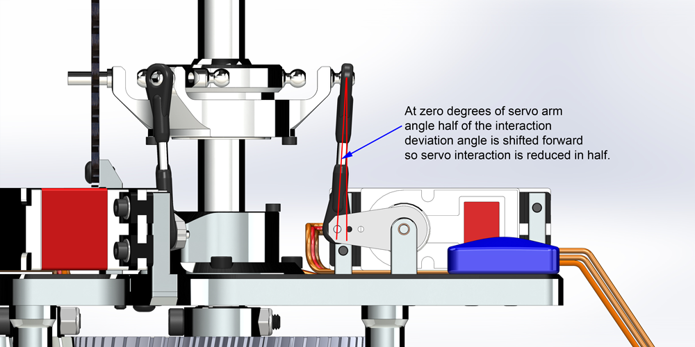
CORRECT DESIGN:
In the first picture we can see how the Mostro’s swashplate to servo linkage rod is slightly shifted forward creating a slight angle when compared to a vertical line. This is done on purpose to minimize the effects of interaction.
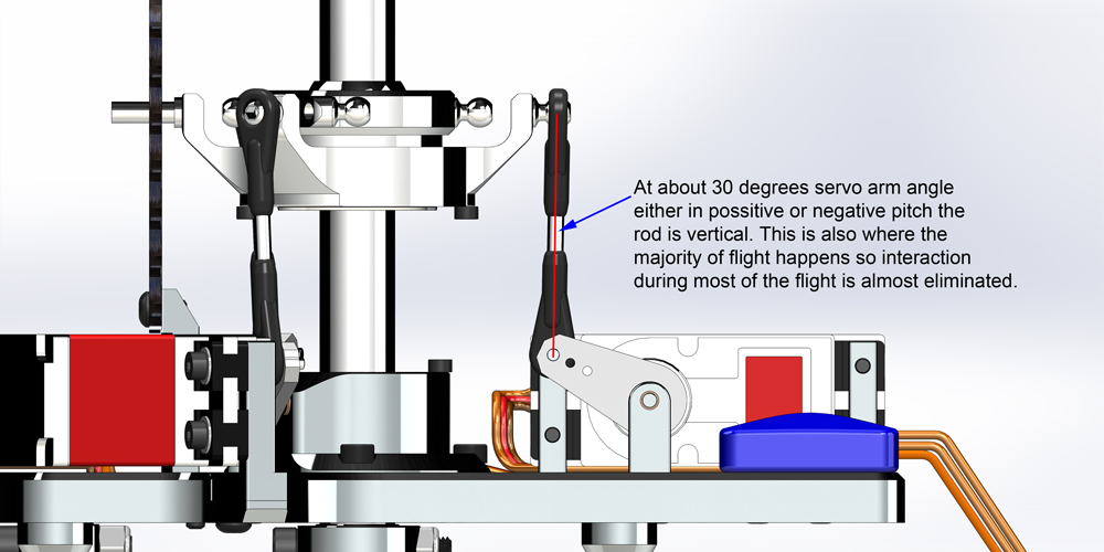
As you can see in the next picture at a slight positive or negative pitch the link is vertical. This is where most of the flying happens because when your helicopter is flying it needs either a positive or negative pitch angle to generate lift and prevent it from falling. This is where you need to try to have the minimum amount of interaction and it’s why at this point it’s vertical.
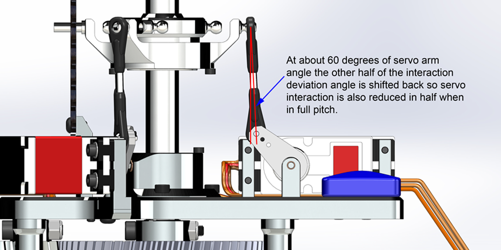
In the next picture you can see that at full pitch the interaction angle now goes the opposite way and it’s half of the total angle cutting in half the potential interaction at full pitch travel.
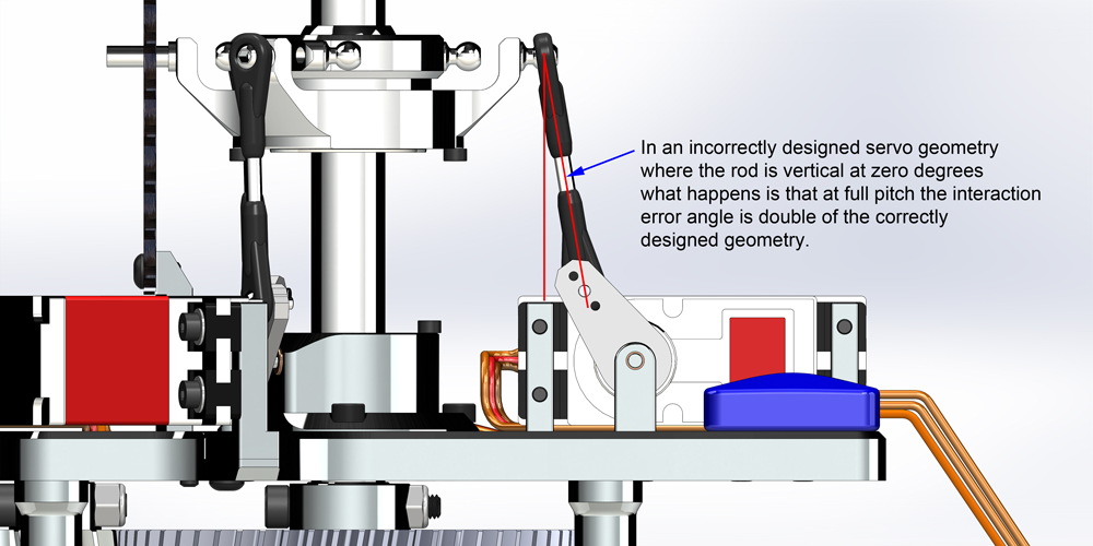
INCORRECT DESIGN:
Compare this to a poorly designed geometry. In this case the rods are vertically aligned and we agree that it looks really pretty because it seems nice and aligned but that where the pretty stops because when full pitch is applied the error from interaction is doubled due to the unnecessarily excessive angle that the fbl system needs to fight against.
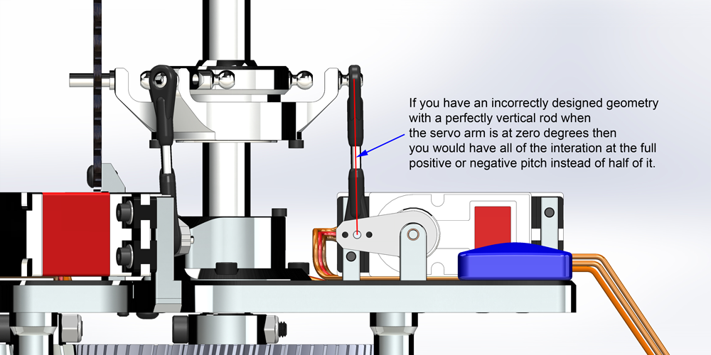
You can see in this picture how a poorly designed geometry can increase the interaction error to double what it could be.
It’s this attention to details that make the Mostro such an amazingly awesome flying machine. You wouldn’t think that this level of attention to details is important but when to many are done in a machine design the result is a superbly flying machine. We will continue with a series of articles about design insights on the Mostro.
Hope this helps people understand how the interaction can be minimized with a properly designed geometry.
Avant RC.